Interface L298N DC Motor Driver Module with ESP8266 NodeMCU
In this tutorial, we will learn to interface L298N Motor Driver with ESP8266 NodeMCU. This is an in-depth guide about the L298N motor driver including its specifications, pinout, interfacing with ESP8266 NodeMCU board. Firstly, we will see an example to control DC motors with it. In the end, we will see an example to control the direction of a DC motor using an L298N motor driver.
We have a guide for ESP32 and ESP8266 using MicroPython:
Table of Contents
L298N Motor Driver Module
The L298N motor driver module is very easy to use with microcontrollers and relatively inexpensive as well. It is widely used in controlling robots as we can connect up to four motors at once but if we want to control the speed and direction as well then it allows two motors to be connected. Thus, it is perfect for two-wheeled robots. This module is mainly used in robotics and in controlling dc and stepping motors.
The L298N motor driver module consists of an L298N motor driver IC, 78M05 5V regulator, 5V jumper enable, power LED, heat sink, resistors, and capacitors all combined in an integrated circuit. The diagram below shows all the components consisting inside the module.
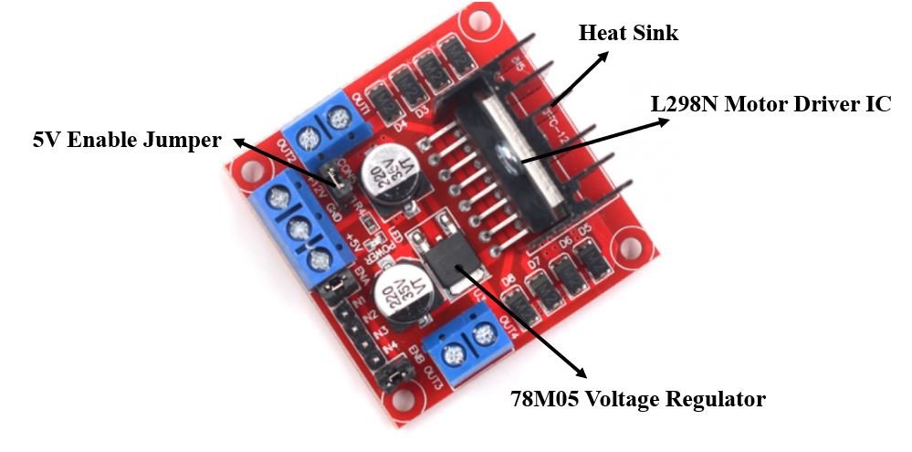
The L298N Motor driver IC is powerfully built with a big heat sink. It is a dual-channel H bridge motor driver which can be easily used to drive two motors.
The module also has a 78M05 5V regulator which is enabled through a jumper. Keeping the jumper intact, means the 5V regulator is enabled. If the motor power supply is less than 12V then we will power the module through the voltage regulator. The 5V pin in this case acts as an output to power the microcontroller. If the power supply is more than 12V, make sure the jumper is not intact and supply 5V power through the pin separately.
Note: If the jumper is connected, do not supply power to both the motor power supply input and the 5V power supply input.
Specifications
The table shows some specifications of the L298N motor driver module:
| Driver Model | L298N |
| Driver Chip | Double H-bridge L298N |
| Maximum Power | 25W |
| Maximum Motor Supply Voltage | 46V |
| Maximum Motor Supply Current | 2A |
| Driver Voltage | 5-35V |
| Driver Current | 2A |
| Size | 43x43x26mm |
PinOut
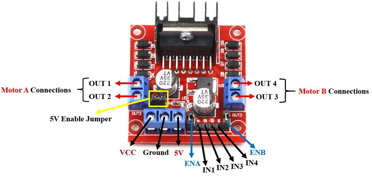
Let us now look at the pinout of the module.
| Pin Name | Description |
| VCC | This is the pin which supplies power to the motor. It is imprinted with +12V on board but can be powered between 6-12V. |
| Ground | This is the common ground pin. |
| 5V | This pin supplies the power (5V) for the internal circuit (L298N IC). Will be used only if the 5V enable jumper is not intact. If jumper is intact, then it acts as an output pin. |
| ENA | This pin controls the speed of the motor A by enabling the PWM signal. |
| IN1 & IN2 | These are the input pins for motor A. They control the spinning direction for that particular motor. |
| IN3 & IN4 | These are the input pins for motor B. They control the spinning direction for that particular motor. |
| ENB | This pin controls the speed of the motor B by enabling the PWM signal. |
| OUT1 & OUT2 | OUT1: Positive terminal. OUT2: Negative terminal These are the output pins for motor A. Motor A having voltage between 5-35V, will be connected through these two terminals. |
| OUT3 & OUT4 | OUT3: Positive terminal OUT4: Negative terminal These are the output pins for motor B. |
Controlling DC motors through L298N Driver Module
Let us now see the details behind controlling the dc motor through the L298N module.
Control Pins
There are two types of control pins found at the bottom right side of the module. One type controls the speed and the other type controls the direction of the motor.
Speed Control (ENABLE) Pins
The speed control pins labeled ENA and ENB on the module, control the speed of the dc motor and turn it ON and OFF.
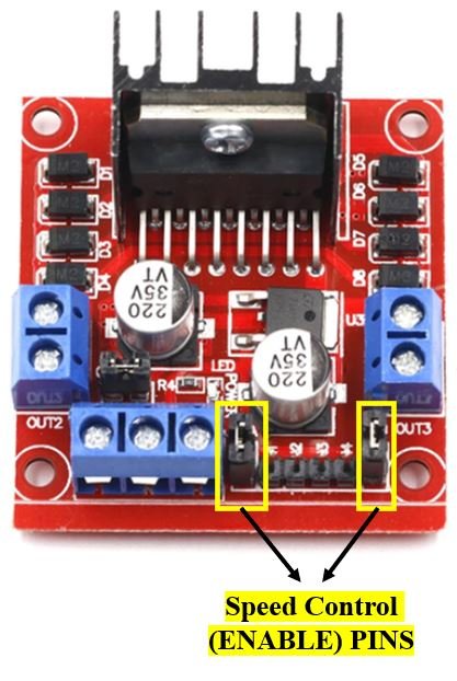
ENA controls the speed of motor A and ENB controls the speed of motor B. If both of the pins are in a logic HIGH (5V) state, then both the motors are ON and spinning at maximum speed. If both of the pins are in a logic LOW (ground) state, then both the motors are OFF. Through the PWM functionality, we can also control the speed of the motor. By default, there is a jumper connected to these pins which keep these pins in a HIGH state. In order to control the speed, we need to remove the jumper and connect these terminals with the PWM pins of ESP8266 and program them in code. The table below demonstrates the logic signals required for controlling Motor A.
| ENA Pin State | Motor Action |
| 1 (HIGH) | ON |
| 0 (LOW) | OFF |
If ENA is in a HIGH state, the motor is enabled and if it is in a LOW state then the motor is off.
Direction Control (INPUT) Pins
The direction control pins are the four input pins (IN1, IN2, IN3, IN4) on the module.
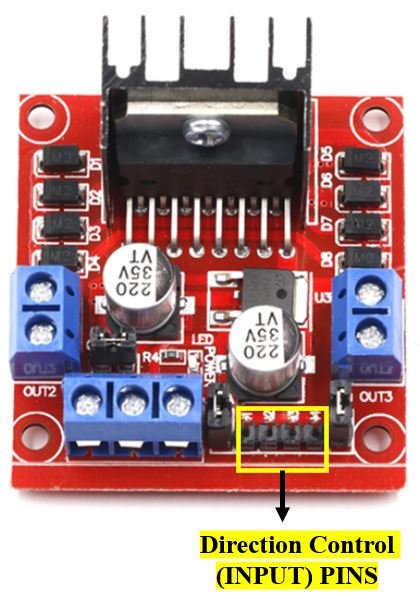
Through these input pins we can determine whether to move the dc motor forward or backwards. IN1 and IN2 control motor A’s spinning direction whereas IN3 and IN4 control motor B’s spinning direction. The table below shows the logic signals required for the appropriate spinning action for motor A.
| IN1 | IN2 | Motor Action |
| 1 (HIGH) | 1 | OFF |
| 1 | 0 (LOW) | Backward |
| 0 | 1 | Forward |
| 0 | 0 | OFF |
As seen from the table, whenever one of the inputs is in a HIGH state (5V) then the motor will spin. Otherwise, when both the inputs are LOW (ground) state or both are in HIGH state then the motor stops. In order for motor A to spin forward, IN1 should be LOW and IN2 should be HIGH. For backwards motion, IN1 should be HIGH and IN2 should be LOW. Motor B is also controlled in a similar way.
Interface L298N DC Motor Driver with ESP8266
Now, as we have seen how to control the dc motor through the motor driver, let us do a demonstration by showing you how to control two DC motors using this driver.
Required Equipment
- ESP8266 board
- L289N Motor driver Module
- External 3-12 V power supply
- DC Motor
- Connecting Wires
Assemble the circuit as shown in the connection diagram below.
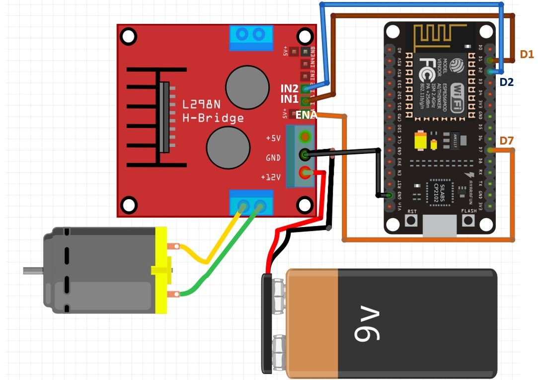
We will be using motor A output pins to control this motor. Thus, ENA will set the speed and IN1 and IN2 will set the spinning direction of the motor.
In ESP8266, PWM is supported through all input output GPIO pins. So
choose any GPIO pin (GPIO0-GPIO16) to connect with the enable pin of the
L298N motor driver. We have used D7 as the PWM pin. In the above
schematic, we can see that D7 is connected with ENA, and IN1 and IN2 are
connected with D1 and D2 respectively.
You can choose appropriate GPIO pins when connecting the ESP board and the driver module together.
The dc motor is rated at 6-12V, and requires a large amount of current to start. This is why we will be using an external power source for the dc motor. As we can use any power source ranging from 6-12V, we will incorporate a 9V battery in our case. You can use any other power source.
We are keeping the 5V Enable jumper in its place as it will power up the L298N motor driver.
Arduino Sketch: Controlling DC Motors using L298N Motor Driver
Open your Arduino IDE and go to File > New. A new file will open. Copy the code given below in that file and save it.
This basic sketch will show us how to control a DC motor’s speed and direction of rotation using the L298N motor driver.
int ENA = D7;
int IN1 = D1;
int IN2 = D2;

void setup() {
  pinMode(ENA, OUTPUT);
  pinMode(IN1, OUTPUT);
  pinMode(IN2, OUTPUT);
  digitalWrite(IN1, LOW);
  digitalWrite(IN2, LOW);
}

void loop() {
  setDirection();
  delay(1000);
  changeSpeed();
  delay(1000);
}

void setDirection() {
  analogWrite(ENA, 255);

  digitalWrite(IN1, HIGH);
  digitalWrite(IN2, LOW);
  delay(5000);

  digitalWrite(IN1, LOW);
  digitalWrite(IN2, HIGH);
  delay(5000);

  digitalWrite(IN1, LOW);
  digitalWrite(IN2, LOW);
}

void changeSpeed() {
  digitalWrite(IN1, LOW);
  digitalWrite(IN2, HIGH);

  for (int i = 0; i < 256; i++) {
    analogWrite(ENA, i);
    delay(20);
  }

  for (int i = 255; i >= 0; --i) {
    analogWrite(ENA, i);
    delay(20);
  }
  digitalWrite(IN1, LOW);
  digitalWrite(IN2, LOW);
}
How the Code Works?
Firstly, we will define the L298N motor driver’s control pins connection with the ESP8266 board. We have used the same pins as shown in the connection diagram above. Make sure the enable pins are connected with PWM enabled pins of the ESP8266 board. For the input pins you can use any digital pin of the board.
int ENA = D7;
int IN1 = D1;
int IN2 = D2;
setup()
Inside the setup() function, first we will configure all the control pins as output pins. This will be done by using the pinMode() function. The pin will be passed as the first parameter and OUTPUT will be passed as the second parameter.
Then by using the digitalWrite() function we will set up all the input pins to a LOW state so that initially the motor is off.
  digitalWrite(IN1, LOW);
  digitalWrite(IN2, LOW);
loop()
Inside the loop() function, we will call the user defined functions setDirection() and changeSpeed() after a delay of 1 second. The first function will be used to control the direction of the motor and the second function will control the speed.
void loop() {
  setDirection();
  delay(1000);
  changeSpeed();
  delay(1000);
}
setDirection()
void setDirection() {
  analogWrite(ENA, 255);

  digitalWrite(IN1, HIGH);
  digitalWrite(IN2, LOW);
  delay(5000);


  digitalWrite(IN1, LOW);
  digitalWrite(IN2, HIGH);
  delay(5000);


  digitalWrite(IN1, LOW);
  digitalWrite(IN2, LOW);
}
The setDirection() function is responsible to control the direction of the motor. The motor can either turn on, off or change their directions. This is done by providing the input pins (IN1 and IN2) with different logic signals. As we have already discussed before, through these input pins we can determine whether to move the dc motor forward or backwards.
First we will set up both the motors at their maximum speed. This will be done by using the analogWrite() function and passing the enable pin as the first parameter and ‘255’ as the second parameter. Here 255 denotes the highest PWM value.
analogWrite(ENA, 255);Then we will first turn the motor ON, then change its direction and then turn it OFF. These three actions will be done after a delay of 5 seconds each. Use digitalWrite() to change the logic state of the pin by passing the pin as the first parameter and the logic state as the second parameter. Follow the table given in the Direction Control Pins, section to set the input pins to required states appropriately.
  digitalWrite(IN1, HIGH);
  digitalWrite(IN2, LOW);
  delay(5000);


  digitalWrite(IN1, LOW);
  digitalWrite(IN2, HIGH);
  delay(5000);


  digitalWrite(IN1, LOW);
  digitalWrite(IN2, LOW);
changeSpeed()
void changeSpeed() {
  digitalWrite(IN1, LOW);
  digitalWrite(IN2, HIGH);

  for (int i = 0; i < 256; i++) {
    analogWrite(ENA, i);
    delay(20);
  }


  for (int i = 255; i >= 0; --i) {
    analogWrite(ENA, i);
    delay(20);
  }

  digitalWrite(IN1, LOW);
  digitalWrite(IN2, LOW);
}
The changeSpeed() function is responsible to control the speed of the motor. As we have already discussed before, the speed control pins labeled ENA and ENB on the module, control the speed of the dc motor.
First, by using the digitalWrite() function turn on the motor by setting the relevant logic states to the input pins.
  digitalWrite(IN1, LOW);
  digitalWrite(IN2, HIGH);
Then we will increase the speed of the motors steadily. By using a for loop we will increment the PWM value from 0 to 255 (maximum speed). This is done through the analogWrite() function which takes in the enable pin as the first parameter and the PWM value as the second parameter.
  for (int i = 0; i < 256; i++) {
    analogWrite(ENA, i);
    delay(20);
  }
Likewise, we will decrease the speed of the motor from a maximum (255) to zero.
  for (int i = 255; i >= 0; --i) {
    analogWrite(ENA, i);
    delay(20);
  }
Lastly, we will turn the motor off by providing a LOW signal to the input pins.
  digitalWrite(IN1, LOW);
  digitalWrite(IN2, LOW);
Demonstration
To see the demonstration of the above code, upload the code to ESP8266. Before uploading the code, make sure to select NodeMCU 1.0 from Tools > Board.

Also, select the correct COM port to which the board is connected from Tools > Port.
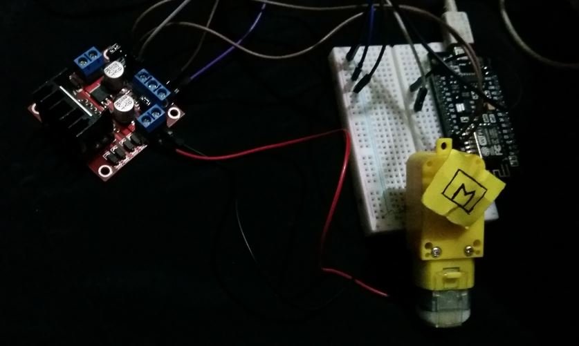
Once the code is uploaded to your board, the motor will start rotating.
First, the motor will start rotating backwards for 5 seconds then they will start rotating forwards for 5 seconds. Then the motor stop. After a delay of 1 second, the motor start speeding up and reach maximum speed then they start slowing down and finally stop. Then the loop starts again.
Control Direction of DC Motor using L298N Motor Driver and ESP8266 NodeMCU
Now let us use a push button as an input to control the direction of the DC Motor. When the push button will be pressed the motor will move in the forward (clockwise) direction and when it will be released then the motor will move in backward (anti-clockwise) direction. We will use a pull down resistor with the push button hence when the button will be pressed the ESP8266 GPIO pin connected with the button will go HIGH.
Required Components:
- ESP8266 module
- L289N Motor driver Module
- External 3-12 V power supply
- DC Motor
- Push button
- 10k ohm resistor
- Breadboard
- Connecting wires
Assemble your circuit as follows:
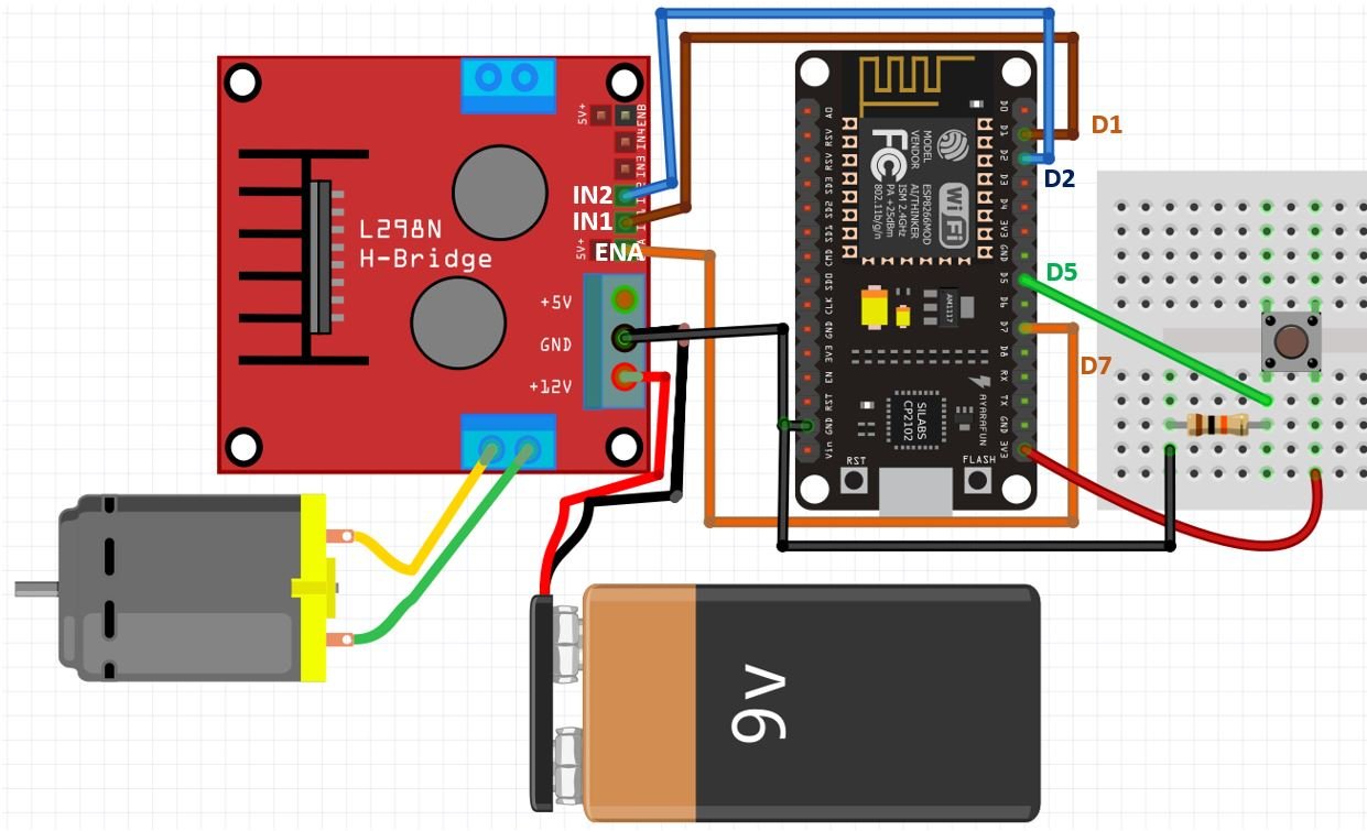
The push-button has four terminals. One terminal is powered by 3.3 volts from ESP8266 and the other terminal is connected by D5 and the 10k ohm resistor which acts as a pull-down resistor. The other end of the resistor is connected with the common ground.
When the push button is pressed, a logic state of high (1) will be passed on D5 and the push button input will be in a high state. When the button is released a logic state of low (0) will be passed on D5 and the push button input will be in a logic state LOW. We will read these two states of the push button and control the direction of the dc motor accordingly.
Arduino Sketch
Open your Arduino IDE and go to File > New to open a new file. Copy the code given below in that file.
int ENA = D7;
int IN1 = D1;
int IN2 = D2;
const int PushButton = D5;

void setup()
{
  pinMode(ENA, OUTPUT);
  pinMode(IN1, OUTPUT);
  pinMode(IN2, OUTPUT);
  pinMode(PushButton, INPUT);
  digitalWrite(IN1, LOW);
  digitalWrite(IN2, LOW);
}

void loop(){
  analogWrite(ENA, 100);
 int Push_button_state = digitalRead(PushButton);
 if ( Push_button_state == HIGH ){
     digitalWrite(IN1, LOW);
     digitalWrite(IN2, HIGH);
     }
 else
    {
     digitalWrite(IN1, HIGH);
     digitalWrite(IN2, LOW);
    }
}
How the Code Works?
Firstly, we will define the ESP8266 connections with the L298N motor driver’s control pins and the push button. We have used the same pins as shown in the connection diagram above.
int ENA = D7;
int IN1 = D1;
int IN2 = D2;
const int PushButton = D5;
Inside the setup() function, first we will configure the control pins as output pins and the push button as the input pin. This will be done by using the pinMode() function. The pin will be passed as the first parameter and OUTPUT or INPUT will be passed as the second parameter. Then by using the digitalWrite() function we will set up the input pins to a LOW state so that initially the motor is off.
void setup()
{
  pinMode(ENA, OUTPUT);
  pinMode(IN1, OUTPUT);
  pinMode(IN2, OUTPUT);
  pinMode(PushButton, INPUT);
  digitalWrite(IN1, LOW);
  digitalWrite(IN2, LOW);
}
loop()
Inside the loop() function we will first read the state of the push button pin using digitalRead() and save it in the integer variable ‘Push_button_state.’ Moreover we have set the speed of the motor using the analogWrite() function and passed the enable pin A as the first parameter and ‘100’ which denotes the PWM as the second parameter. The PWM can take values from 0-255 where 255 is the maximum speed.
 analogWrite(ENA, 100);
 int Push_button_state = digitalRead(PushButton);
Then if the push button state is HIGH meaning the button is pressed we will set the dc motor to move in forward direction. This is done by using the digitalWrite() function and passing the input pin as the first parameter and the state as the second parameter. The dc motor spins forward whenever IN1 goes in a LOW (0) state and IN2 goes in a HIGH (1) state.
if ( Push_button_state == HIGH ){
     digitalWrite(IN1, LOW);
     digitalWrite(IN2, HIGH);
     }
However, if the push button is not pressed then the dc motor will spin backwards.
else
    {
     digitalWrite(IN1, HIGH);
     digitalWrite(IN2, LOW);
    }
Demonstration
To see the demonstration of the above code, upload the code to ESP8266. Before uploading the code, make sure to select NodeMCU 1.0 from Tools > Board.
Also, select the correct COM port to which the board is connected from Tools > Port.
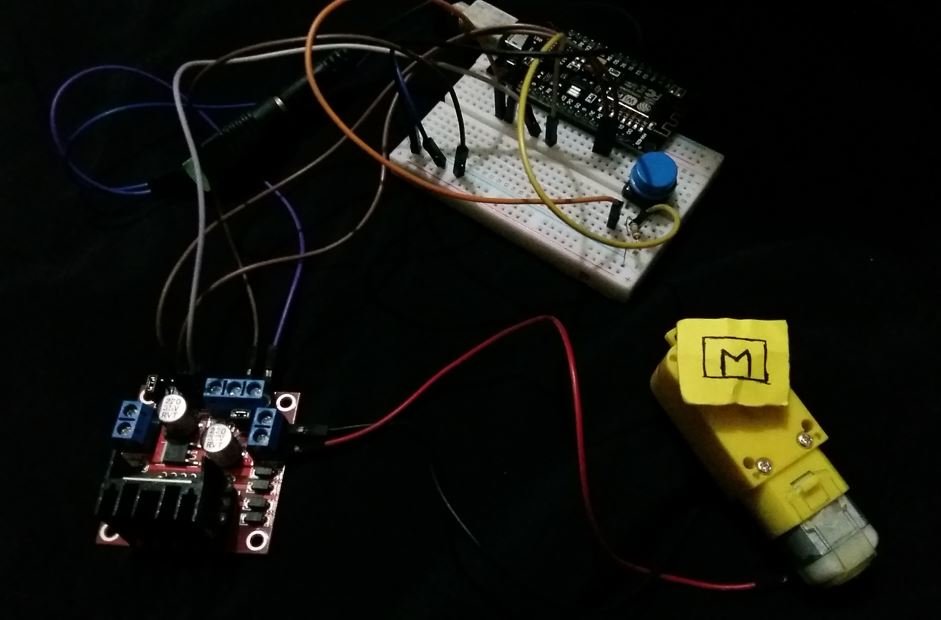
Once the code is uploaded to your board, the motor will start rotating.
Now press the push button and the dc motor will start spinning in the forward (clockwise) direction. When you release the button, the dc motor starts spinning in the opposite direction.
No comments:
Post a Comment